
How to design a better pulse oximeter Implementation Circuit Diagram In this project we are going to learn how to make a pulse oximeter with the ability to measure heart rate and blood oxygen. First let's make the circuit, make sure to follow the exact circuit diagram since the program is designed accordingly. 2.

A pulse oximeter is a non-invasive device used to measure the oxygen saturation level (SpO2) in the blood and pulse rate. It works by emitting light through a part of the body, usually a fingertip, and measuring the amount of light absorbed by the blood. Required Components: Simple Pulse Oximeter. 1. ESP32 Module (Buy from Amazon) 2. MAX30100 pulse oximeter sensor (Buy from Amazon) 3. 4.7k ohm resistors (Buy from Amazon) 4. OLED Display (Buy from Amazon) 5.Vero Boards (Buy from Amazon) 6. Connecting wires. (Buy from Amazon)7.
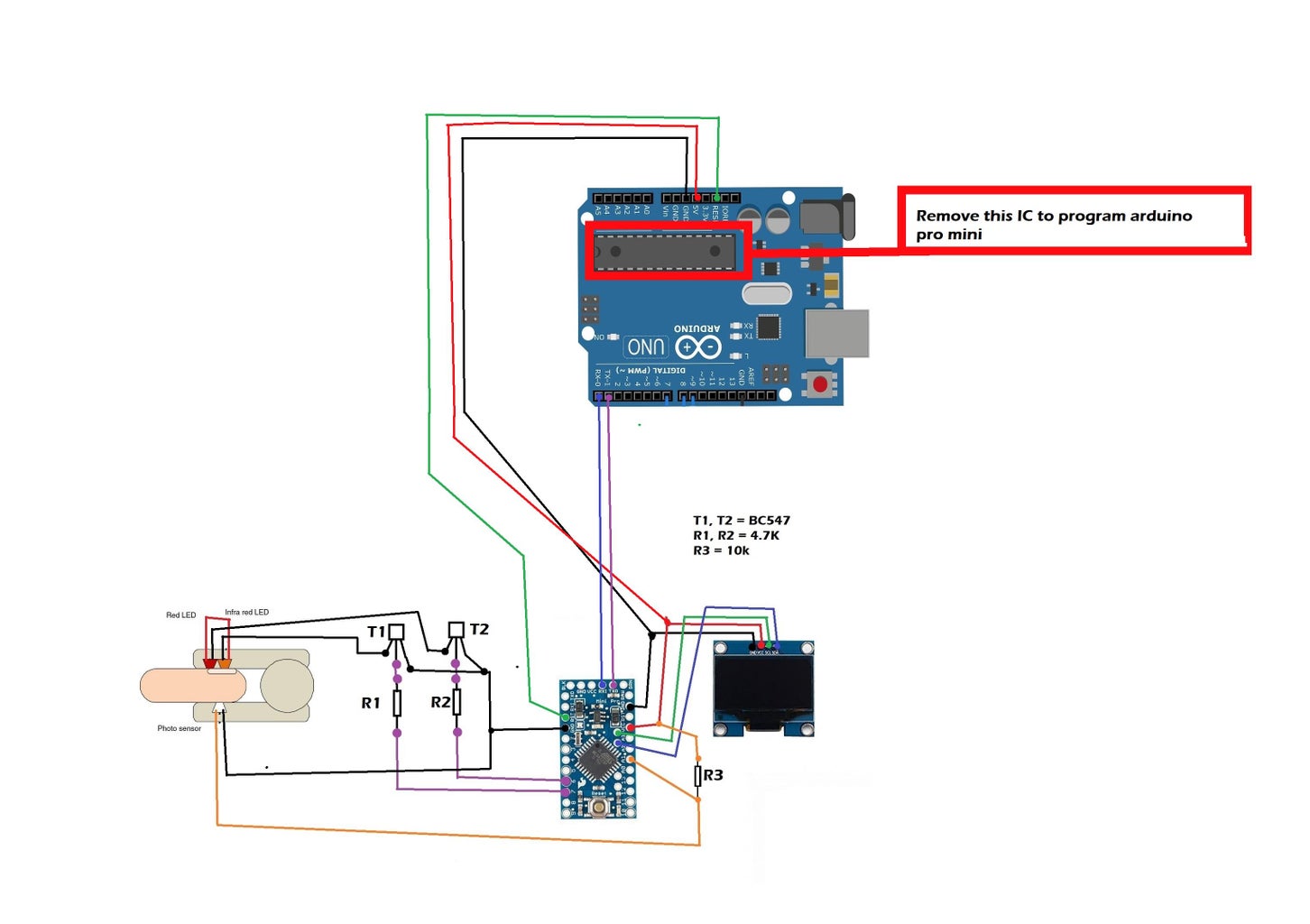
Compact Arduino Based Pulse Oximeter Sensor Circuit Circuit Diagram
The oximeters can also build By using Max30100 Sensor which is specially design for measuring pulse and oxygen saturation in blood. It's not that critical to make an pulse oximeter using it, since It combines two LEDs, a photodetector, optimized optics, low-noise analog signal processing to detect pulse oximetry and heart-rate signals. and I2C interface.

Fortunately, pulse oximeters are relatively easy to make at home with some basic knowledge of electronics and an understanding of how the circuit works. The first step is to gather the components. You'll need an infrared LED and photodiode, resistors, a microcontroller with an analog-to-digital converter, and a display.

Arduino Pulse Oximeter : 35 Steps (with Pictures) Circuit Diagram
Basic pulse oximeter circuit. The signal contains DC and AC components. The DC component is due to constant reflective matter such as skin, muscle and bone, and venous blood. When a body is at rest and motion is less of a factor, the AC component comprises mainly of reflected light from the pulsation of artery blood. The AC component depends on
The "SpO2" reading on a pulse oximeter shows the percentage of oxygen in someone's blood. If your home SpO2 reading is lower than 95%, call your health care provider. I want to minimize this DIY design, so here in the PCB I am using Arduino Nano MCU, 16*2 LCD, MAX30100 with charging circuit. This is tested schematics, but the LCD only
